Virtualizing pfSense on ESXi with One NIC
Disclaimer: Before we get started, I want to point out that I do not recommend deploying this setup as-is for production. I built this solution to work around some hardware limitations I have in my homelab, an environment I use for learning and experimentation. Only build this solution in a sandbox environment.
I recently purchased some cheap hardware so that I can start building my homelab. Naturally, one of the first tasks I wanted to pursue was to separate my lab and home networks. Here is the architecture that I achieved:
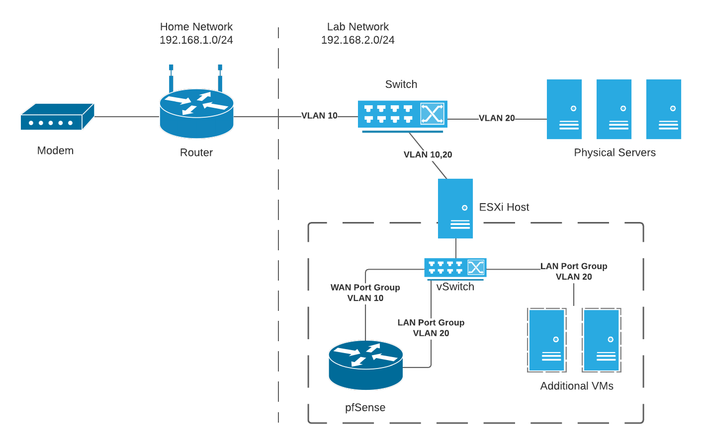 Network architecture described in this post
The primary component I want to talk about in this blog post is the virtual pfSense running on ESXi. Because my physical switch does not have Layer 3 capabilities, I needed to deploy a router in the lab network to communicate outside of the LAN. And, because I only have a few physical nodes right now, I didn’t want to dedicate an entire node for running pfSense. So, I decided to virtualize pfSense on ESXi.
Here’s the challenge – my nodes only have one NIC, whereas pfSense should be installed on a node with at least two NICs (one for WAN and another for LAN).
Now, I could (and will at some point) purchase better hardware to improve this architecture. But I also wanted to take this as an opportunity to experiment to see if I can get this working. In this post, I will talk about the steps I took to virtualize pfSense on ESXi with one NIC to install a router for my lab network.
Switch Configuration
First, let’s cover my switch’s configuration. I’m using a Netgear ProSafe GS108PEv3 managed switch. I configured it with two VLANs:
- VLAN 10 – Home router on Port 1 and my ESXi host on Port 7.
- VLAN 20 – Lab nodes (including the ESXi host) on Ports 2-8.
Below are VLAN Membership screenshots from my switch’s management page. On my switch, VLANs are configured under VLAN -> 802.1Q -> Advanced -> VLAN Membership.
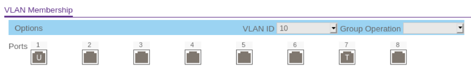 VLAN 10 (Home router and ESXi host)
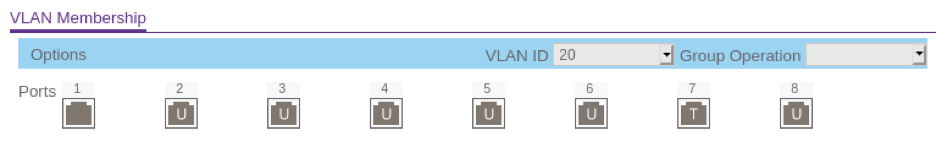 VLAN 20 (Lab nodes, including the ESXi host)
Notice that Port 7 says T, while the other ports say U. The “T” means “tagged”, which is required on port 7 since the ESXi host will send and receive packets from both VLAN 10 and VLAN 20. The other ports are marked “U”, which means “untagged”.
I also configured the Port PVID settings, with each port matching the VLAN ID that we assigned above.
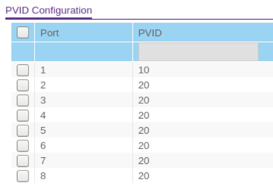 Port PVID Configuration
That’s it for configuring the switch. Let’s take a look at the ESXi config next.
ESXi Configuration
The primary challenge in configuring ESXi was sharing a single vSwitch across pfSense, management, and other VMs, since my host only has one NIC. Below shows the vSwitch topology that I landed on to get things working.
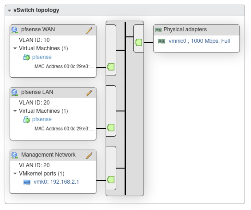 vSwitch Topology
As you can see in the topology above, I created three Port Groups on the default vSwitch, vswitch0:
- pfSense WAN – This is the interface connecting pfSense to the internet. This is tagged as VLAN 10 so that pfSense can reach the internet through my home router.
- pfSense LAN – This interface serves as the default gateway for lab machines (both physical and virtual). It is tagged as VLAN 20, the same ID as ports 2-8 on my switch.
- Management Network – This is the IP address used for managing ESXi. I moved this from VLAN 0 (default) to VLAN 20 to reside on the same VLAN as my lab servers.
To provide another view at my port groups, here are the same port groups displayed again on the Port Groups page:
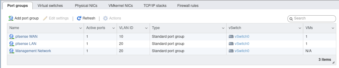 Port Groups page
Once I configured ESXi’s networking details, I uploaded a pfSense iso to a datastore. I downloaded the iso from pfSense’s downloads page. To understand how to upload the iso, refer to VMware’s doc, Upload ISO Image Installation Media for a Guest Operating System.
Finally, I created the pfSense virtual machine by selecting “Virtual Machines” in the navigator and clicking “Create/Register VM”. Below shows a screenshot of my VM settings.
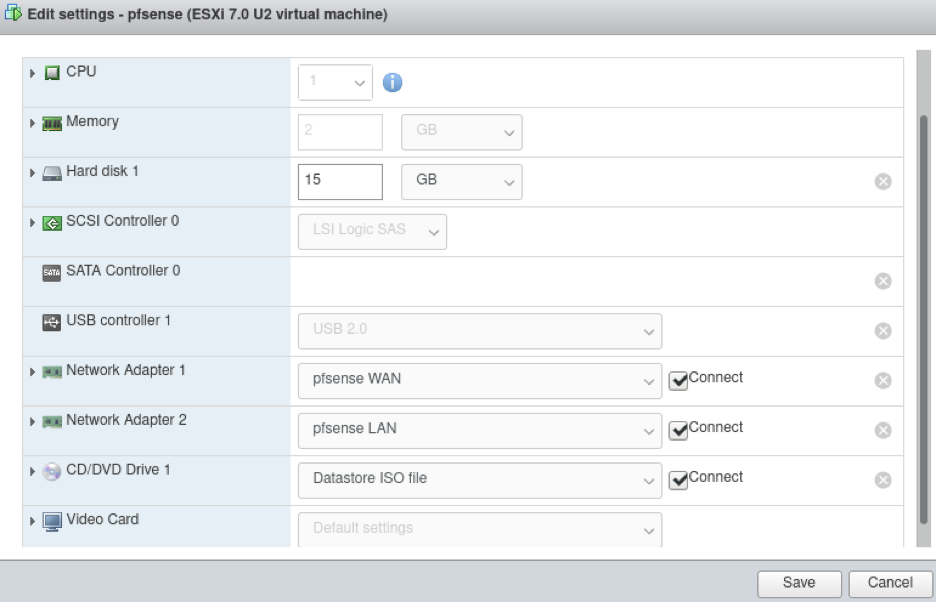 pfSense VM Settings
The key thing to keep in mind is the Network Adapter settings. I set Network Adapters 1 and 2 to pfSense WAN and pfSense LAN, respectively. I also allocated 1 CPU and 2 GB memory to the VM. I need to do further analysis to determine the optimal resources, though it may depend case by case.
With ESXi configured, we’re almost there! Let’s talk about the pfSense installation next.
pfSense Installation and Configuration
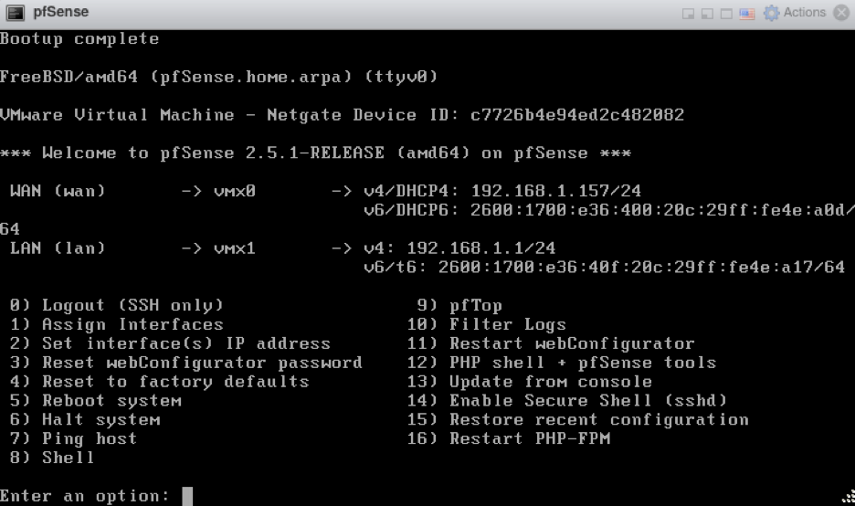
The pfSense installation begins by starting the pfSense VM. This process was simple since all of the default options worked for me. After the installation completed, I rebooted the VM and saw the “Should VLANs be set up now?” option, shown below:
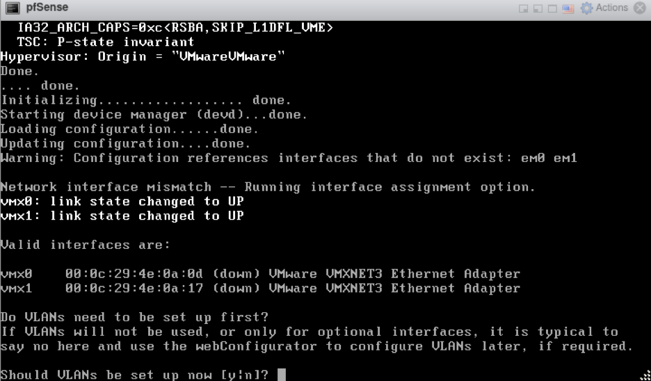
I didn’t need to set up VLANs here, so I entered n.
Next, I was asked to enter the WAN and LAN interface names, which are vmx0 and vmx1, respectively. After about a minute or so, I saw the following screen:
 Auto-assigned WAN and LAN IP addresses
At this point, we are close, but not quite finished. While pfSense attempted to configure its own WAN and LAN IP addresses (the former assigned by DHCP), neither were the IP addresses I wanted. I wanted to give a static IP address for WAN, and I wanted to move the LAN IP to my lab network. First, to avoid collisions, I removed the IP addresses from both WAN and LAN by entering the option “2” and following the prompts to provide “None” as the desired IP address. My prompt screen then looked like this:
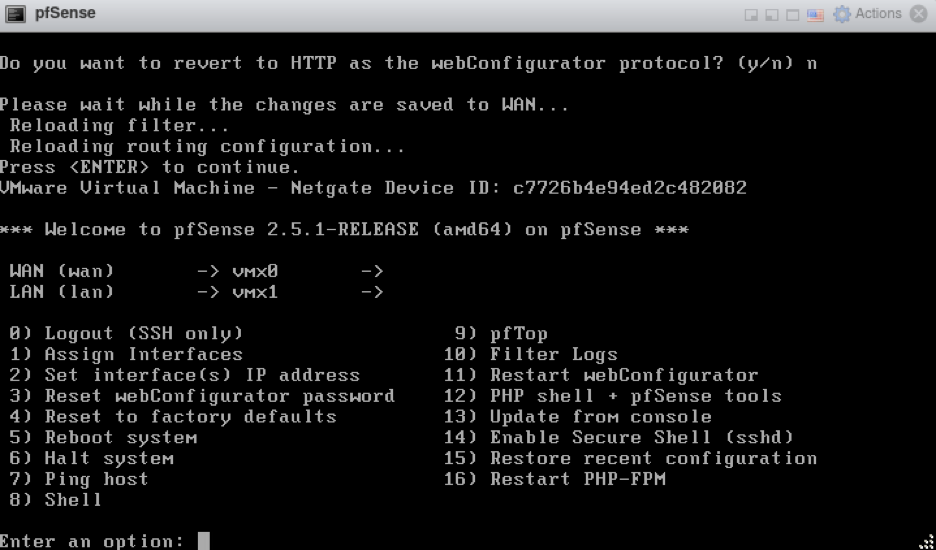 WAN and LAN IP addresses are both blank
Once both WAN and LAN were blank, I assigned the correct IP addresses by entering the option 2. Here are the settings that I used:
- WAN: 192.168.1.1/24 (gateway – 192.168.1.254)
- LAN: 192.168.2.254/24 (DHCP disabled)
My final WAN and LAN configuration looked like this:
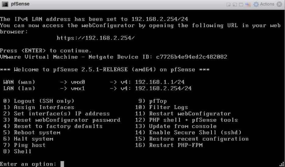 WAN and LAN IP addresses are assigned appropriately
By now, pfSense was “technically” working. I could set 192.168.2.254 as the default gateway and DNS server for hosts on the lab network, and I could ping an address like “8.8.8.8”. But when I tried to ping a hostname like “google.com”, it didn’t work! To fix this, I needed to log into webConfigurator at https://192.168.2.254 (credentials admin/pfsense) and, under Interfaces -> WAN, I needed to uncheck Block private networks and loopback addresses.
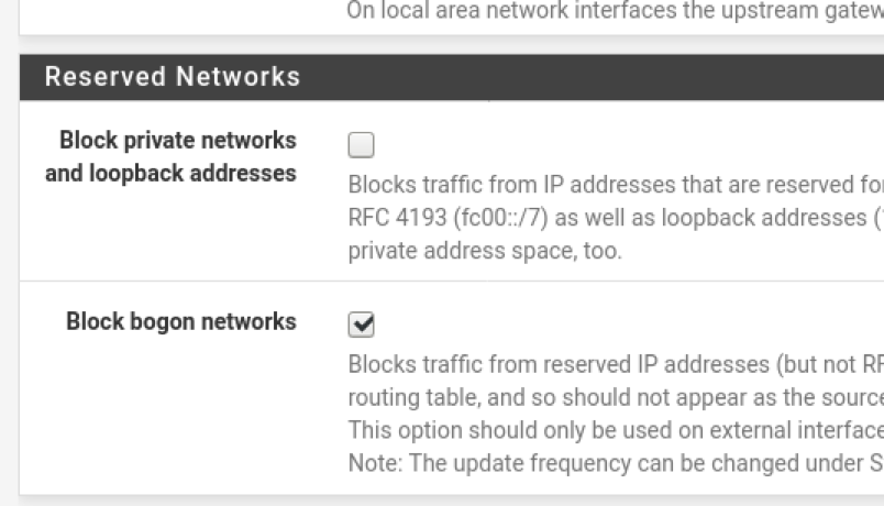 “Block private networks and loopback addresses” needs to be unchecked
I speculate that this is required for your home router and DNS (residing on a private network) to return a domain name’s IP address to pfSense.
Now, with this option unchecked, I was able to access the internet and resolve domain names from lab machines, all while remaining on a separate network from the rest of my home!
Thanks For Reading
I hope you found this blog post helpful. There are, of course, many more items that I could have configured in pfSense, but this represents the minimum configuration I needed to virtualize pfSense on ESXi with one NIC. Do reach out if you have any questions, and I’ll see you next time.